About this part
FEA Studio writes its reports as paginated, Word-like documents that you can read on screen, print, or save as PDF, Word or HTML. This part covers:
- the project reports (model, analysis and design);
- the calculation sheets of single members, footings and connections;
- the other outputs: images, CSV files and charts.
Project information
Reports take their project details from the project sheet. Click the project name at the top of the Explorer to see it in Properties.
| Field | Where it appears |
|---|---|
| Name | Page header, report cover and subtitle |
| Description | Cover and title block, when filled in |
| Unit system | All values in the report, and the Units line on the cover |
The file name, region, design codes, and created and modified dates are added automatically. Save the project before you make a report, so the file name appears instead of "Not saved".
Project reports
The three reports
| Report | Available | Contents |
|---|---|---|
| Model report | When the model has geometry or an imported mesh | Project and design codes; geometry with isometric, plan and front views; structural grid; members, shells and solids; materials and sections; supports; load cases, loads and combinations; the mesh |
| Analysis report | After at least one analysis | Summary of studies; method and sign conventions; for each study: set-up, frequencies (modal), load cases and combinations, extreme values, member forces, support reactions, solver notes |
| Design report | After a static or nonlinear analysis | Summary with pass and fail counts; failing designs; design basis (codes, materials, load cases); one chapter per design type; step-by-step calculations of footings and connections |
Making a report
- Choose File › Reports › Model report, Analysis report or Design report. Or go to stage 8 Reports in the Explorer and double-click the report you want (or right-click it › Generate report).
- A progress card shows each stage, for example "Pictures of the model" and "Laying out pages". To take the pictures, the 3D view briefly switches to the light theme; your camera and theme are restored afterwards.
- The report opens as a tab in the centre, next to the 3D view. Making the same report again reuses its tab.
The Report… button in the Design summary (Part 3) opens the Design report directly.
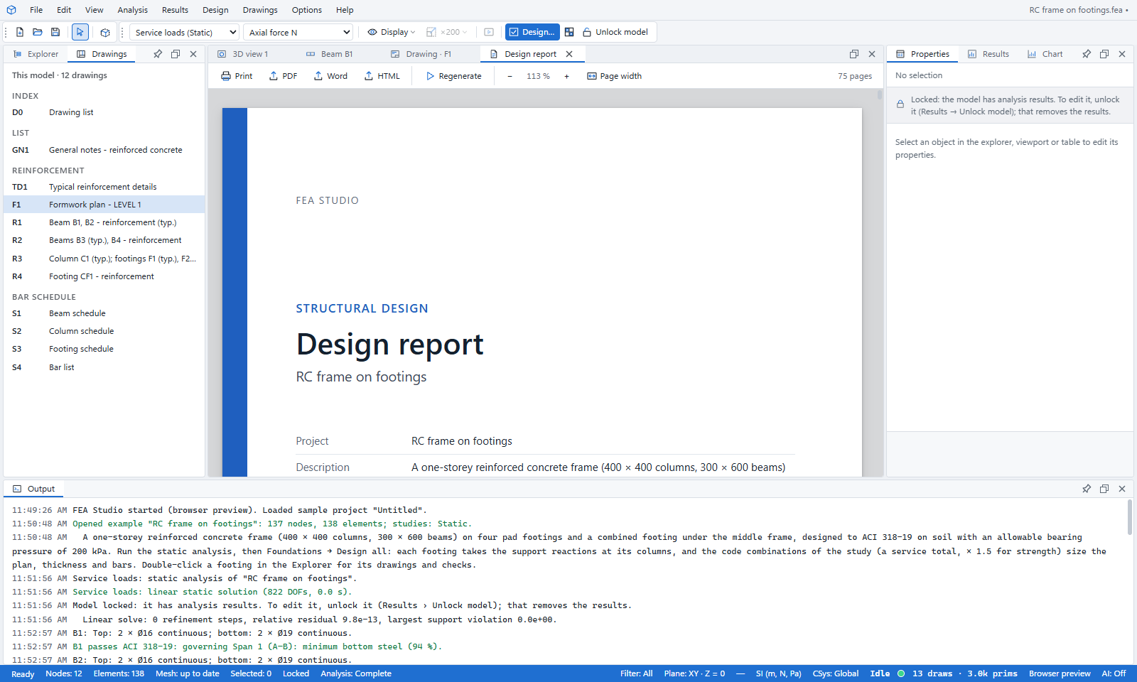
The report tab
| Button | What it does |
|---|---|
| Prints the report | |
| Saves it as a PDF document | |
| Word | Saves it as a Word document (.docx) |
| HTML | Saves it as a web page |
| Regenerate | Builds the report again from the current model and results |
| − · % · + | Zoom out, the zoom level, zoom in (50 % to 200 %) |
| Page width | Fits the page width to the window (the default) |
The right end of the toolbar shows the number of pages. Click an entry in the contents to jump to that section.
Tip. After you change the model or the design, click Regenerate. A report shows the state at the moment it was made.
Page layout
Every report uses the same layout, on screen and in print, PDF and HTML:
- Paper: A4 portrait.
- Header on every page: FEA Studio, the project name and the report title.
- Footer: the date and time, the file name, and "Page X of Y".
- Cover page:
- the report kind, for example "Structural design";
- the title and project, and a table of project facts;
- a picture of the model;
- for the Design report, a verdict box: green when all designs pass, red with the number that fail;
- a revision and sign-off table: Rev., Date, Description, Prepared, Checked, Approved.
- Contents, with page numbers.
- Numbered sections (1, 1.1, 1.1.1). Chapters start on a new page, and table headers repeat on every page.
Note. The Prepared, Checked and Approved cells on the cover are left blank, ready for signatures. Reports have no company logo field; the logo and firm fields belong to the drawing title blocks (Part 4).
Design report in detail
The Design report starts with a summary table, one row per design type:
| Column | Meaning |
|---|---|
| Design · Code | The design type and its code |
| Items · Pass · Fail · Not checked | Counts |
| Highest utilisation | The largest ratio and where it occurs |
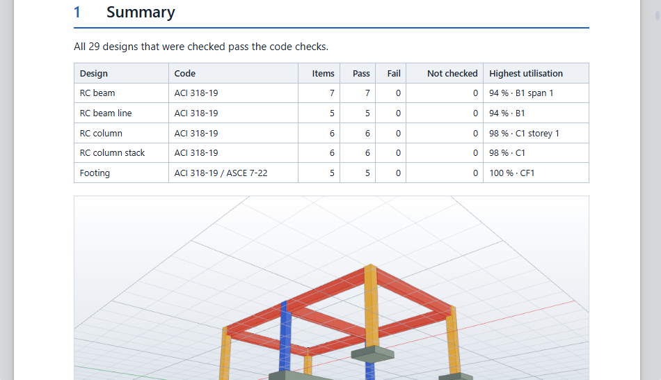
Each design type then has its own chapter. A table lists every item with its name, scope, size, reinforcement, utilisation, governing check and status (OK, Fails, Not designed or Not checked). Failing rows come first, then the rest sorted by utilisation.
Footings and connections add step-by-step calculations. Each one shows the formula, the values put into it and the result, with OK or fail marks and notes.
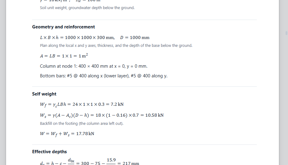
For the step-by-step calculations of concrete beams, columns, slabs, steel, composite members and walls, use their calculation sheets (next section), or the classic report with Detailed calculations.
Calculation sheets
Members
Every designed concrete beam line, column stack, slab, steel member, joist, composite member, wall pier, spandrel and shell has its own tab (Part 3). To open it, double-click the item in the Explorer, or tick Calculation sheet in its Properties.
The tab's toolbar has:
- Detailed calculation: shows every check step by step, with its equations. Print, PDF and Word include the calculation while it is shown. The setting is remembered.
- Print, PDF and Word.
The output is one document with a title block: the member name and the code standards.
Summary (Design › Concrete › Design, or Design › Foundations › Design) gives a table of all beam lines or all footings, with Print…, PDF… and Word….
Footings
- Design › Foundations › Report › Calculation report reports the selected footing. Report of all footings reports every footing. The Generate report button on a footing tab does the same.
- The report holds:
- a summary and the design basis;
- for each footing: its drawings (plan and section), load cases, combinations, reinforcement, moment and shear, code checks and the step-by-step calculation.
Connections
- Design › Connections › Report › Generate report… reports the selected connections, or all of them. You can also right-click a connection or the Connections folder › Generate report.
- The report holds:
- a summary and the design basis: code, materials, load cases and analysis method;
- for each connection: members and parts, load effects, CBFEM analysis results, plates, bolts and anchors, welds, concrete in bearing, buckling, component checks and detailing notes.
The classic Analysis report (File › Report)
File › Report (Ctrl+P) makes one combined document. It contains the model, a picture of the current 3D view, materials, sections, mesh, supports and loads, the results of each study, and a section from each design module.
- Choose File › Report or press
Ctrl+P. - The Analysis report dialog says how many sections and result sets the report covers.
- Tick Detailed calculations (the equations of every design check) to include every design equation. This option appears when a design module has detail to add.
- Click PDF… (the default), Word…, Print… or Web page….
Saving and printing
| Format | What you get | Notes |
|---|---|---|
| The laid-out pages on the printer | Pages are A4 and carry their own margins, so the printer adds none | |
| A PDF file | Desktop: a save dialog, then a progress card. Browser: the print dialog opens; choose "Save as PDF" or "Microsoft Print to PDF" as the printer. | |
| Word (.docx) | An editable Word document | Real headings, a Word table of contents, header and footer with page numbers, repeating table headers, equations as Word equations, and pictures |
| HTML | A single web page | The same pages, viewable in any browser |
Reports are named after the project file and the report, for example "Bridge - Design report.docx". Every save is logged in the Output panel.
Note. When you open a Word report for the first time, Word may ask to update the fields. Answer Yes to fill in the table of contents and page numbers.
In the desktop app, a bar appears after each save, titled Saved with the file name and folder:
- Open folder opens the folder in File Explorer with the file selected.
- Open file opens the file in its usual app.
Other outputs
| Output | Command | Contents |
|---|---|---|
| Image of the 3D view | File › Export › Viewport image (PNG) | The active view as shown, in the current theme |
| Results as CSV | Results › Tools › Export CSV | The frame shown: node displacements, element stresses, beam end forces and support reactions |
| Results table | Results › Tools › Results table | Every result of the frame shown, sortable and filterable, saved as CSV |
| Mesh tables | File › Export › Nodes (CSV), Elements (CSV) | Node and element lists |
| Charts | Chart › CSV, SVG, Print, PDF, Word | The chart and its data; printed charts are landscape |
| Drawing lists | Drawings › Export › Save lists (CSV)… | Bill of materials and bar bending schedule (Part 4) |
| Model exchange | File › Export | Abaqus, MIDAS, Nastran, VTK and IFC files (Part 1 and Part 2) |
Which report to use
| You need | Use |
|---|---|
| A record of the model for checking | Model report |
| Analysis results to submit or archive | Analysis report |
| The design of the whole structure with pass and fail counts | Design report |
| Full calculations of one member | Its calculation sheet with Detailed calculation on |
| Footing or connection calculations | Calculation report / Generate report in Foundations or Connections |
| One document with everything | File › Report (Ctrl+P) with Detailed calculations |